

Date | 2026-07-09 13:12:36
Designing insulation for low-voltage switchgear, energy storage converters, or EV chargers often forces engineers into a frustrating trade-off: leave enough creepage distance for safety, but don't waste precious internal space. The fix isn't simply adding more ribs or slots — it starts upstream, with the material’s Comparative Tracking Index (CTI). Here, we break down how IEC 60664-1 links voltage, pollution degree, and material group, and why Bulk Molding Compound (BMC) with a CTI ≥ 600 V unlocks design efficiencies that standard engineering plastics cannot match.
Under IEC 60664-1, creepage distance depends on four parameters:
Working voltage – the steady-state voltage the insulation must withstand, including DC values and, where applicable, any superimposed ripple.
Pollution degree – a classification of the micro-environment:
PD1: sealed, no pollution or only dry non-conductive dust.
PD2: typically non-conductive pollution but occasional condensation (indoor equipment).
PD3: conductive pollution or frequent condensation (unsealed industrial or outdoor cabinets).
PD4: persistent conductive contamination (rain, snow, conductive dust).
Material group – determined by the CTI value (comparative tracking index) of the insulating material:
Group I: CTI ≥ 600 V
Group II: 400 V ≤ CTI < 600 V
Group IIIa: 175 V ≤ CTI < 400 V
Group IIIb: 100 V ≤ CTI < 175 V
Insulation type – functional, basic, supplementary, or reinforced, each with its own multiplication factor.
The takeaway: for a given voltage and pollution degree, the higher the material group, the shorter the required creepage distance. Selecting a Group I material is one of the most direct ways to shrink insulation dimensions without compromising safety.
Let's put the standard into practice. Consider a battery combiner cabinet operating at 1,500 V DC, installed in an unsealed industrial enclosure where condensation can occur (pollution degree 3). The insulation is basic insulation.
Working voltage: Un = 1,500 V DC
Pollution degree: 3
Insulation type: basic
Material: BMC 16XX (Wenzhou Jintong) with PTI ≥ 600 V → Material Group I
Consulting the relevant table in IEC 60664-1, the required creepage distance for this combination is approximately 16.0 mm.
Now, what if the designer had chosen a common glass-fiber reinforced PA66 (CTI ~400 V, Material Group II)? The required distance jumps to about 20.0 mm. For an unfilled PC/ABS blend (CTI ~250 V, Group IIIa), it exceeds 25.0 mm.
Table 1: Required Creepage Distance for 1,500 V DC / Pollution Degree 3 / Basic Insulation, by Material Group
| Material Group | CTI/PTI (V) | Typical Material | Creepage Distance (ref.) | Increase vs. Group I |
|---|---|---|---|---|
| I | ≥ 600 | BMC (Jintong 16XX) | ~16.0 mm | — |
| II | 400–599 | PA66-GF flame-retarded | ~20.0 mm | +25% |
| IIIa | 175–399 | PC/ABS | ~25.0 mm | +56% |
| IIIb | 100–174 | Ordinary phenolic | ~32.0 mm | +100% |
Note: Values are interpolated from IEC 60664-1 typical conditions. Always consult the official standard for exact requirements. Minor variations may exist between editions.
The design payoff: shrinking the creepage distance from 20 mm to 16 mm means the busbar support insulator can be 20% narrower. That allows shorter busbar spans, lower resistive losses, and higher power density within the same cabinet envelope — an elegant way to tackle system miniaturization without re-engineering the entire layout.
Tracking occurs when moisture and an electric field conspire to form a conductive carbon path on an insulator’s surface. BMC resists this process through three mechanisms:
High inorganic filler loading (alumina trihydrate, etc.): endothermically decomposes under arc heat, releasing water vapor and suppressing carbon formation.
Crosslinked unsaturated polyester matrix: the three-dimensional network contains strong C–C bonds that won't readily degrade into free carbon chains.
Optimized fiber–matrix interfaces: minimize micro-cracks and prevent moisture ingress that could create local high-field spots.
In standard CTI testing per IEC 60112 (solution A), Wenzhou Jintong's BMC grades repeatedly withstand 600 V without erosion, firmly placing them in Material Group I. This has been validated across thousands of applications in circuit breakers, contactors, and energy storage insulators.
Even with a Group I material, a few pitfalls can sabotage creepage clearance:
Ineffective ribs: IEC 60664-1 qualifies a rib as “effective” only if it is at least 2.5 mm high and 2.5 mm wide at the base. Narrow, shallow ribs may not count.
Surface pollution: accumulated salt spray or oil mist creates a semi-conductive film. For outdoor installations, consider hydrophobic coatings or periodic cleaning.
DC voltage factor: DC is more aggressive than AC for tracking (no zero-crossing to extinguish arcs). Many designers apply a 1.2–1.3× factor to the creepage distance obtained from AC-based tables, or conduct specific DC tracking tests.
Alignment with other standards: photovoltaic applications must also satisfy IEC 62109; railway applications need EN 45545-2 for fire protection on top of insulation coordination.
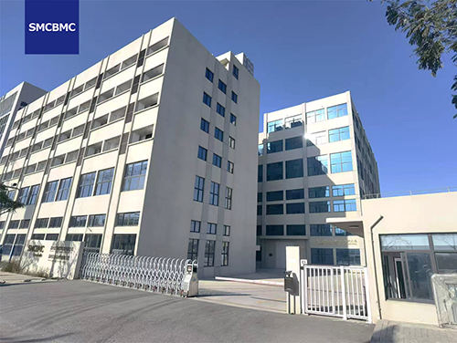
Wenzhou Jintong has been producing BMC/SMC thermoset materials since 2001. All 16XX, 17XX, and 18XX series products carry PTI ≥ 600 V (Material Group I) and have UL Yellow Card certification. Our internal standard Q/JTJ0001-2025 mandates PTI as a routine batch test, ensuring lot-to-lot consistency.
For new projects, we offer:
Full material group verification reports (including CTI/PTI test data per IEC 60112).
Application support for creepage distance calculations and insulation-coordination reviews.
Sample plaques or prototype parts for your internal validation.
Custom formulations to fine-tune flammability, temperature index, or shrinkage while retaining Group I performance.
As system voltages climb and device footprints shrink, choosing the right insulation material group becomes a strategic decision — not just a compliance checkbox. Let’s build a safer, more compact design, together.
📧 wendy.qiu@smcbmc.com📞 +86-13868305300