
Date | 2026-07-27 14:03:38
Electrical insulation and thermal conduction live on opposite sides of the materials spectrum. Great insulators—ceramics, mica, thermoset molding compounds—block current, and they block heat just as effectively. Standard BMC and SMC carry a thermal conductivity of 0.2 to 0.6 W/(m·K), roughly the same as still water. For a circuit-breaker housing or a contactor base that generates modest heat, this is perfectly acceptable.
But power density is climbing fast. An EV onboard charger. An 800 kW ultra-fast charging connector. An IGBT module support inside a solar inverter. A plastic-encapsulated motor stator. These components generate real heat in normal operation. If that heat cannot escape, local temperatures rise, insulation ages prematurely, and—in the worst case—thermal runaway follows. Industry data already shows BMC motor end-caps with integrated cooling channels achieving thermal conductivities around 1.2 W/(m·K), proving the concept works in production.
This raises a question that would have sounded contradictory a decade ago: can you make an electrical insulator that also conducts heat?
On October 10, 2025, that question got its own product standard.
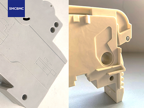
The China Electrical Equipment Industry Association (CEEIA) published T/CEEIA 905-2025 — Glass-Fiber-Reinforced Unsaturated Polyester Molding Compounds with High Thermal Conductivity for Electrical Insulation — alongside its anti-static counterpart, T/CEEIA 904-2025. Both took effect on the day of publication.
Wenzhou Jintong and its affiliated materials subsidiary, Wenzhou Huhe New Materials Co., Ltd., were among the industry contributors to this first-edition standard.
The standard's introduction states the problem plainly: "Conventional glass-fiber-reinforced molding compounds have relatively low thermal conductivity and cannot meet the heat-transfer requirements of electrical equipment." The standard positions its products for "medium- and low-voltage circuit breakers, new-energy vehicles, household appliances, and certain heat-generating components."
Table 1: Performance Requirements per T/CEEIA 905-2025
| No. | Property | Unit | BMC Requirement | SMC Requirement |
|---|---|---|---|---|
| 1 | Flexural strength | MPa | ≥ 120 | ≥ 170 |
| 2 | Charpy impact (unnotched) | kJ/m² | ≥ 30 | ≥ 70 |
| 3 | Deflection temperature (Tf1.8) | ℃ | ≥ 240 | ≥ 240 |
| 4 | Dielectric strength (in oil) | kV/mm | ≥ 18 | ≥ 22 |
| 5 | Volume resistivity | Ω·m | ≥ 1.0×10¹² | ≥ 1.0×10¹² |
| 6 | Proof Tracking Index (PTI) | — | ≥ 600 | ≥ 600 |
| 7 | Arc resistance | s | ≥ 180 | ≥ 180 |
| 8 | Flammability | class | V-0 | V-0 |
| 9 | Glow-wire flammability index (GWFI) | ℃ | ≥ 960 / 3.0 | ≥ 960 / 3.0 |
| 10 | Density | g/cm³ | 1.70–2.10 | 1.60–2.00 |
| 11 | Mold shrinkage | % | ≤ 0.15 | ≤ 0.15 |
| 12 | Water absorption | % | ≤ 0.2 | ≤ 0.2 |
| 13 | Thermal conductivity (at 50℃) | W/(m·K) | ≥ 1.3 | ≥ 1.0 |
| 14 | Temperature Index (TI) | — | ≥ 130 | ≥ 130 |
The headline number is line 13. For the first time, a standard draws a bright line: if your BMC doesn't reach 1.3 W/(m·K) — or your SMC doesn't reach 1.0 W/(m·K) — it isn't "thermally conductive." Compared with standard BMC/SMC at 0.2–0.6 W/(m·K), these thresholds represent a two- to six-fold improvement in heat-transfer capability.
Equally significant: the electrical and flammability requirements did not relax to accommodate thermal performance. PTI remains ≥ 600 V (Material Group I per IEC 60664-1). Flammability stays at V-0. Glow-wire performance holds at 960°C. This is not a trade-off; it's an upgrade that preserves the existing safety envelope.
Heat moves through solids by two mechanisms. Metals use free electrons (copper ≈ 400 W/(m·K)). Insulators and semiconductors rely on phonons — quantized lattice vibrations.
Standard BMC/SMC cures into a three-dimensional crosslinked polyester network. That network is mechanically robust, but its amorphous molecular structure scatters phonons relentlessly. The result: thermal conductivity stuck below 1 W/(m·K).
The engineering solution borrows a concept from electrically conductive plastics: build a percolation network of high-thermal-conductivity filler particles inside the polymer matrix. When the filler volume fraction crosses the percolation threshold, particles touch and bridge, creating continuous "thermal highways" that bypass the low-conductivity resin. Heat follows the filler network while voltage stays blocked by the resin.
Common industrial filler families:
| Filler | Intrinsic Thermal Conductivity (W/(m·K)) | Strengths | Limitations |
|---|---|---|---|
| Alumina (Al₂O₃) | ~30–40 | Best cost-performance ratio, excellent electrical insulation, chemically stable | Upper limit on thermal enhancement |
| Boron nitride (BN) | ~250–300 (in-plane) | Exceptionally high conductivity + dielectric strength | Higher cost, anisotropic |
| Aluminum nitride (AlN) | ~170–200 | Very high conductivity | Hydrolysis-sensitive; environment must be controlled |
| Silicon carbide (SiC) | ~80–120 | Hard, wear-resistant | Electrical insulation slightly below oxides |
Production-grade formulations almost always use hybrid filler systems. A typical approach: alumina builds the primary thermal skeleton at high loading; a smaller fraction of boron nitride fills the interstitial gaps between alumina particles, improving network density. Particle-size distribution, surface treatment (coupling agents to strengthen the resin–filler interface), and the shear history during compounding collectively determine the final thermal conductivity — and its batch-to-batch consistency.
The standard mandates thermal conductivity measurement per GB/T 29313 at 50°C — a temperature representative of steady-state operation inside most electrical enclosures, and more relevant than room-temperature values.
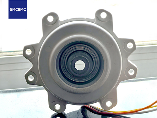
The engineering value proposition is straightforward: one part now does two jobs. It insulates electrically and conducts thermally.
Table 2: Application Map
| Industry | Typical Parts | Recommended Grade | Why It Matters |
|---|---|---|---|
| New-energy vehicles | OBC/DCDC housings, PTC heater brackets, motor end-caps | BMC (≥ 1.3 W/(m·K)) | Power semiconductors generate concentrated heat; a thermally insulating housing forces derating or invites premature failure |
| Ultra-fast charging | Charging-gun seats, HV relay bases, insulating barriers | BMC (≥ 1.3 W/(m·K)) | 800 kW liquid-cooled chargers push hundreds of amps through connectors; the insulator sits in the thermal path and must not become the bottleneck |
| Motor encapsulation | Stator encapsulation, fractional-horsepower motor shells | BMC (≥ 1.3 W/(m·K)) | Copper and iron losses in the winding generate substantial heat; the encapsulant's thermal conductivity directly governs the motor's temperature rise and power-density ceiling |
| Solar inverters | IGBT module supports, heatsink spacer pads | SMC (≥ 1.0 W/(m·K)) | Inverter power ratings continue climbing; the insulating support must transfer heat from the power die to the heatsink across a large contact area. Public data indicates BMC inverter housings can reduce cost versus die-cast metal |
| Home appliances | Induction-cooker coil brackets, heating-element bases | BMC (≥ 1.3 W/(m·K)) | Structural parts in direct contact with heat sources; thermal conductivity directly affects the appliance's thermal-protection strategy and end-user safety |
| LV/MV switchgear | High-current breaker housings, busbar support barriers | SMC (≥ 1.0 W/(m·K)) | Conductor heat dissipates through the insulating support to the enclosure; better conductivity means lower busbar temperature rise — or smaller copper cross-sections for the same current rating |
When deciding whether to specify a thermally conductive grade, follow this logic:
Step 1: Identify the heat-source power density.If the insulating part sits directly against a power semiconductor, motor winding, or busbar carrying high continuous current, and the heat flux exceeds roughly 0.5 W/cm², evaluate a high-conductivity grade. If the part only sees ambient temperature with no direct contact to a heat source, standard BMC/SMC is likely sufficient.
Step 2: Map the thermal path and find the bottleneck.Draw the series thermal resistance chain from heat source to ambient. If the insulator is the only low-conductivity element in that chain — the rest being copper, aluminum, or thermal grease — then upgrading to a thermally conductive BMC/SMC will reduce overall junction temperature systematically.
Step 3: Verify voltage withstand and flammability.For 1500 V DC storage or high-voltage contactor applications, confirm PTI ≥ 600 V and dielectric strength ≥ 18 kV/mm (BMC) or ≥ 22 kV/mm (SMC). For applications requiring both V-0 and 960°C glow-wire, verify the grade covers this combination.
Step 4: Check the toughness trade-off.Higher filler loading improves thermal conductivity but can reduce impact strength. The standard floors are 30 kJ/m² for BMC and 70 kJ/m² for SMC. Request the supplier's thermal-conductivity-vs-impact-strength curve to confirm both parameters stay within your design window.
Step 5: Address moldability.Thermally conductive formulations carry higher filler loadings, which increase compound viscosity. This affects mold-filling behavior and may require adjustments to gate location, venting strategy, or clamping profile. Conduct a joint process review with the material supplier before tooling is finalized.
Wenzhou Jintong has focused on BMC/SMC thermoset materials and molding since 2001. Its thermally conductive capability rests on three pillars:
Formulation. Jintong has developed multiple thermally conductive BMC/SMC grades. Using hybrid filler systems of alumina and boron nitride with optimized coupling-agent surface treatment, these formulations raise thermal conductivity from the standard 0.2–0.6 W/(m·K) to 1.3–2.0 W/(m·K) — meeting and exceeding the T/CEEIA 905-2025 thresholds — while preserving PTI ≥ 600 V, V-0 flammability, and dielectric strength ≥ 18 kV/mm.
Processing. Highly filled compounds demand disciplined process control. Jintong's internal process standard Q/JTJ0002-2025 specifies three-stage mold-closing speed profiles, multi-step degassing (2–3 venting cycles at 70–80% fill, each ≤ 0.8 seconds), and post-cure hold times of 15–30 seconds — parameters tuned to accommodate the rheology of highly filled formulations without filler agglomeration or uneven cure.
Validation. Jintong supplies full thermal conductivity test reports per GB/T 29313 at 50°C, alongside dielectric strength (GB/T 1408.1), volume resistivity (GB/T 31838.2), tracking resistance (GB/T 4207), and arc resistance (GB/T 1411) data. These datasets support customers' thermal simulations and component-level temperature-rise testing.
Electrification — in vehicles, in energy storage, in solar, in charging infrastructure — is pushing insulation materials beyond their traditional single-function role. The insulator now has to carry heat as well as block voltage. T/CEEIA 905-2025 gives design engineers something they didn't have before: a quantified, testable, standards-based definition of "thermally conductive BMC/SMC."
Wenzhou Jintong, as a contributor to the standard, supplies grades that meet its requirements and supports custom formulation to hit specific thermal-conductivity targets.
For technical data sheets, grade recommendations, or a discussion about your thermal-management requirements:
📧 wendy.qiu@smcbmc.com📞 +86-13868305300